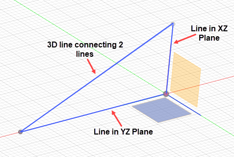
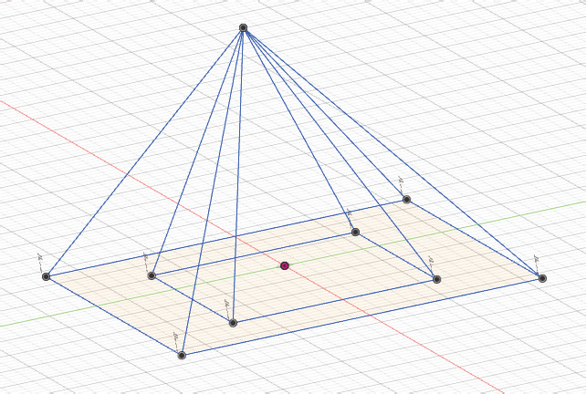
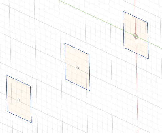
3D Sketches are those sketches which are not confined to single plane. Assume a line connecting end points of two lines in YZ and ZX planes; refer to Figure-1. Such a sketch can be called 3D Sketch; refer to Figure-2.
In Autodesk Fusion 360, there are no specific tools for creating 3D sketches except a check box to enable or disable 3D sketching in SKETCH PALETTE. So, we are back to basics of plane orientations for creating 3D sketches. The process of creating a 3D sketch is explained next with the help of an example.
Creating 3D Sketch in Autodesk Fusion 360
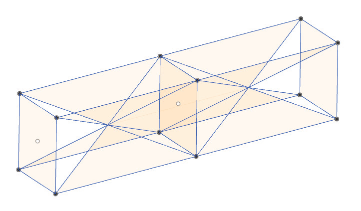
Create the sketch of frame as shown in Figure-3.
Creating Base Sketches and Planes
• After starting a new design fi le in Autodesk Fusion, click on the Create Sketch button from the CREATE drop-down. You will be asked to select a sketching plane.
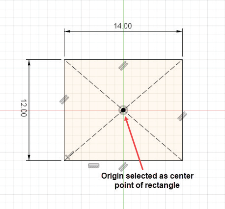
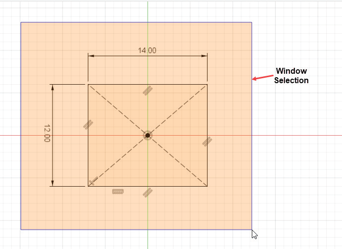
• Select the XY plane as sketching plane and create a center point rectangle as shown in Figure-4.
• Nope! Don’t exit the sketching environment yet!! Select the whole sketch by window selection; refer to Figure-5 and press CTRL+C from keyboard. This will keep a copy of current sketch in clipboard memory of software.
• Click on the Finish Sketch button from FINISH SKETCH panel of the Toolbar to exit sketching environment.
• Click on the Off set Plane tool from the CONSTRUCT drop-down of the SOLID tab in the Toolbar and select XY Plane from Origin node of BROWSER; refer to Figure-6.
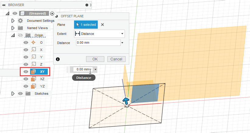
• Specify the distance value as 300 in OFFSET PLANE dialog box and click on the OK button. A new plane will be created at a distance of 300 from XY plane.
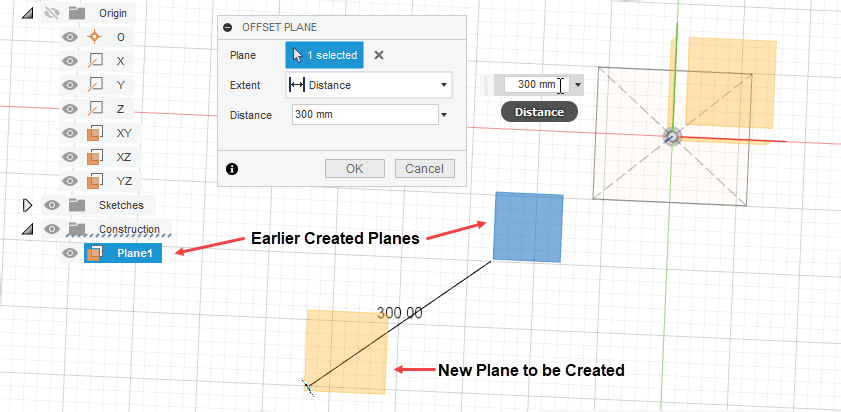
• Click again on the Off set Plane tool from the CONSTRUCT drop-down in the Toolbar and create another plane at an offset distance of 300 from earlier created plane; refer to Figure-7.
• Select Plane1 from the Construction node in BROWSER and click on the Create Sketch button from CREATE drop-down in the Toolbar. The sketching environment will be activated.
• Press CTRL+V from keyboard to paste earlier copied sketch. The MOVE/COPY dialog box will be displayed with sketch pasted; refer to Figure-8.
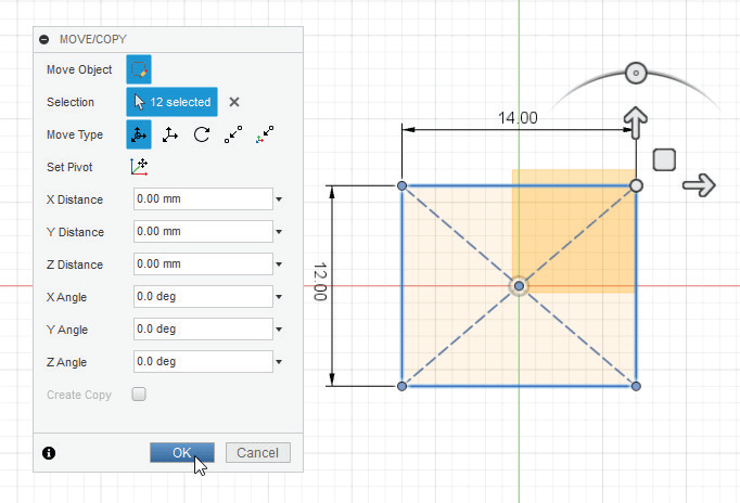
• There is no need to change any parameter because our sketch is well constrained and same as we wanted. Click on the OK button from the dialog box and exit the sketching environment.
• Create the same sketch on other offset plane. The sketches will be displayed as shown in Figure-9.
Creating 3D Lines
• Click on the Preferences option from the User Account drop-down at the top-right corner of the application window. The Preferences dialog box will be displayed.
• Select the Design option from General node at the left in the dialog box. The options will be displayed as shown in Figure-10.
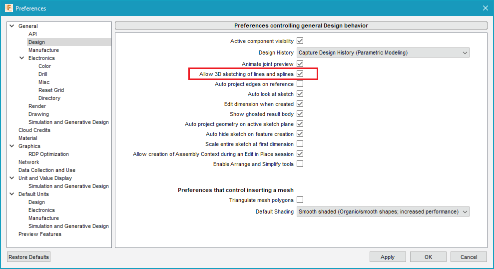
• Select the Allow 3D sketching of lines and splines check box as highlighted in above figure and click on the OK button from the dialog box.
Now, we are ready to create 3-dimensional lines.
• Click on the Create Sketch tool from the CREATE drop-down in the Toolbar and select any of the sketching plane. The sketching plane will become parallel to screen.
• Rotate the model by using SHIFT+Middle Mouse Button (MMB).
• Click on the Line tool from CREATE drop-down and hover the cursor on earlier
created sketches. You will fi nd that the snap points of all the sketches get
highlighted when you hover the cursor over them.
• Now what left is just clicks and clicks. Join various points of sketches to form
frame sketch as shown in Figure-11.

• Click on the Finish Sketch tool from the FINISH SKETCH panel of the Toolbar to exit the sketching environment. So, it is the property of snap points for various elements that allow creating 3D sketch entities.
You can know more about Autodesk Fusion 360 by following our book Autodesk Fusion 360 Black Book (V 2.0.12670) – https://cadcamcaeworks.com/product/autodesk-fusion-360-black-book-v-2-0-12670-part-1-paperback/
For Autodesk Fusion 360 book and other CAD, CAM, and CAE books please visit the link https://cadcamcaeworks.com/shop/