AutoCAD Electrical Group Training: Join Our Comprehensive Training Program!
Why Choose Our AutoCAD Electrical Group Training?
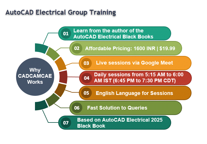
Learn from the author of the AutoCAD Electrical Black Books in our structured program! This course is designed to equip you with essential knowledge and practical skills in just a few weeks, enabling you to excel in your career.
Training Details
- Course Fee: 1600 INR (India) | $19.99 (Rest of the World)
- Language: English
- Syllabus: Based on the AutoCAD Electrical 2025 Black Book (recommended but not mandatory for enrollment)
- Platform: Online training via Google Meet
- Timing: Daily from 5:15 AM to 6:00 AM IST (Indian Standard Time) starting from 20th October 2024. In USA, timing will be 6:45 PM to 7:30 PM CDT (Central Daylight Time) starting from 19th October 2024.
Meet Your Trainer
Gaurav Verma has over 10 years of experience in Electrical, Mechanical, and Civil engineering CAD, CAM, and CAE software. He is the author of the AutoCAD Electrical Black Books and SolidWorks Electrical Black Books and has authored more than 50 skill training courses. Gaurav has also been a speaker at Autodesk University for the AutoCAD Electrical session.
How to Register
To secure your spot in our AutoCAD Electrical group training, simply click Add to cart and follow the procedure. Limited seats are available, so act quickly! Be sure to provide your email address during registration to get enrolled in the list of participants.
For Indian Participants:
Indian customers pay at UPI ID: cadcamcaeworks@okicici or scan the next QR code to pay their fees and send the confirmation message/screenshot to +91-7878065072 or email to cadcamcaeworks@gmail.com
Syllabus
Introductions
Need of Drawings
Electrical Drawings
Circuit Diagram
Wiring Diagram
Wiring Schedule
Block Diagram
Parts list
Symbols in Electrical Drawings
Conductors
Connectors and terminals
Inductors and transformers
Resistors
Capacitors
Fuses
Switch contacts
Switch types
Diodes and rectifiers
Earthing
Wire and Specifications
Types of Wires
Wire specifications
Labeling
Cable Markers
Introduction to AutoCAD Electrical
System requirements for AutoCAD Electrical
Installing AutoCAD Electrical
Starting AutoCAD Electrical
Creating a new drawing document
Meaning of Default templates
Title Bar
Changing Color Scheme
Application Menu
New options
Creating Drawings
Creating Sheet Sets
Open Options
Opening Drawing File
Opening Drawing from AutoCAD Web & Mobile
Save
Save As
Import
Export
Publish
Sending Part for 3D Printing
File Tab Bar
Drawing Area
Command Window
Bottom Bar
Drafting Settings dialog box
Workflow in AutoCAD Electrical
Initializing Project
Project Properties
Project Settings tab
Components tab
Wire Numbers tab
Cross-References tab
Styles tab
Drawing Format tab
Opening a Project File
New Drawing in a Project
Refresh
Project Task List
Project Wide Update or Retag
Drawing List Display Configuration
Plotting and Publishing
Plot Project
Publish to DWF/PDF/DWFx
Zip Project
Removing, Replacing, and Renaming Drawings in a Project
Locations View in Project Manager
Filter by Installation and Location
Search box
Details and Connections tabs
Utilities
Marking and Verifying DWGs
Configuring Catalog Database
Migrating Database to SQL Server
Previous DWG and Next DWG
Migration Data from Previous AutoCAD Electrical Version
Language Conversion in Project
Editing Language Database
Title Block Setup
Title Block Update
Updating Component Based on Changes made in Catalog
Electrical Components
Setting Symbol Library for Project
Inserting Component Using Icon Menu
Component Tag area
Catalog Data area
Description Area
Cross-Reference Area
Installation Code and Location Code
Pins area
Catalog Browser
User Defined List
Equipment List
Panel List
Pneumatic Components
Hydraulic Components
P&ID Components
Symbol Builder
Adding New Symbol in Icon Menu
Introduction
Wires
Wire
22.5 Degree, 45 Degree, and 67.5 Degree
Interconnect Components
Gap
Multiple Bus
Creating Multiple Wire Bus
Ladders
Insert Ladder
XY Grid Setup
X Zones Setup
Wire Numbering
Wire Numbers
3 Phase
PLC I/O
Wire Number Leaders and Labels
Wire Number Leader
Wire Color/Gauge Labels
In-Line Wire Labels
Markers
Cable Markers
Multiple Cable Markers
Insert Dot Tee Markers
Insert Angled Tee Markers
Circuit Builder
Recalculating Wire Size
Introduction
Edit Tool
Internal Jumper
Fix/Unfix Tag
Copy Catalog Assignment
User Table Data
Delete Component
Copy Component
Edit Circuits drop-down
Copying Circuit
Moving Circuit
Saving Circuit to Icon Menu
Transforming Components drop-down
Scooting
Aligning Components
Moving Component
Reversing or Flipping Component
Re-tagging Components
Toggle NO/NC
Swap/Update Block
Swapping
Updating
Edit Attribute drop-down
Moving/Showing Attributes
Editing Selected Attribute
Hiding Attribute (Single Pick)
Hiding Multiple Attributes
Unhiding Multiple Attributes
Adding Attribute to Component
Renaming Attribute
Squeezing Attribute/Text
Stretching Attribute/Text
Changing Attribute Text Height and Width
Rotating Attribute
Changing Attribute/Text Justification
Changing Attribute Layer
Cross References drop-down
Component Cross-Reference
Hide/Unhide Cross-Referencing
Update Stand-Alone Cross-Referencing
Changing Cross-Reference to Multiple Line Text
Cross-Reference Check
Child Location/Description Update
Copying/Adding Component Override
Removing Component Override
Generating Cross-Reference Table
Circuit Clipboard panel
Editing Wires or Wire Numbers
Edit Wire Number
Fix
Swap
Find/Replace
Hide and Unhide
Trim Wire
Delete Wire Numbers
Move Wire Number
Add Rung
Revise Ladder
Renumber Ladder Reference
Wire Editing
Stretch Wire tool
Bend Wire tool
Show Wires
Check or Trace Wire tool
Wire Type Editing drop-down
Create/Edit Wire Type
Change/Convert Wire Type
Flip Wire Number
Toggle Wire Number In-Line
Advanced Wire and Wire Number Editing Tools
Toggle Angled Tee Markers
Flip Wire Gap
Delete Wire Gap
Check/Repair Gap Pointers
Editing Wire Sequence
Show Wire Sequence
Update Signal References
Introduction
Specifications of PLCs
Inserting PLCs (Parametric)
Insert PLC (Full Units)
Addressing Area
Used Area
Tag
Options
Line1/Line2
Manufacturer
Catalog
Assembly
Catalog Lookup
Description
I/O Point Description Area
List descriptions
Pins
Show/Edit Miscellaneous
Ratings
Connectors
Insert Connector
Insert Connector (From List)
Insert Splice
Terminals
Inserting Terminals from Catalog Browser
Associate Terminals on the Same Drawing
Break Apart Terminal Associations
Show Terminal Associations
Edit Jumper
Introduction
Icon Menu
Schematic List
Manual
Manufacturer Menu
Balloon
Wire Annotation
Panel Assembly
Editor
Properties
Terminal
Spare
Destinations, Jumper, and Multilevel
Catalog Code Assignment
Table Generator
Insert Terminals
Insert Terminals (Schematic List)
Insert Terminals (Manual)
Editing Footprints
Edit
Copy Footprint
Delete Footprint
Resequence Item Numbers
Copy Codes drop-down
Copy Assembly
Introduction
Reports (Schematic)
Bill of Materials reports
Component report
Wire From/To report
Component Wire List report
Connector Plug report
PLC I/O Address and Description report
PLC I/O Component Connection report
PLC Modules Used So Far report
Terminal Numbers report
Terminal Plan report
Connector Summary report
Connector Details report
Cable Summary report
Cable From/To report
Wire Label report
Missing Catalog Data
Dynamic Editing of Reports in Drawing
Modifying Tables
Modifying Rows
Modifying Columns
Merge Cells
Match Cells
Table Cell Styles
Edit Borders
Text Alignment
Locking
Data Format
Block
Field
Formula
Manage Cell Content
Link Cell
Download from source
Electrical Audit
Drawing Audit
Signal Error/List
Introduction to Autodesk Inventor
Creating Electro Mechanical Link
Creating New Electromechanical link
Using Existing Electromechanical Link in AutoCAD Electrical
Linking Inventor Model with AutoCAD Electrical Drawing
Electrical Harness in Autodesk Inventor for AutoCAD Electrical
Creating Electrical components in Autodesk Inventor
Placing multiple pins on part
Harness Properties of Part
Creating Wiring in Harness Assembly
Creating Cable
Creating Ribbon Cable
Creating Fold in Ribbon Cable
Automatic Route
Manual Routing
Unrouting wires
For your queries, please write to us at cadcamcaeworks@gmail.com
© 2024 CADCAMCAE Works. All rights reserved.